We offer a bespoke service for ABS Grade DH36 marine steel plates
- May 08, 2026
Knowledge
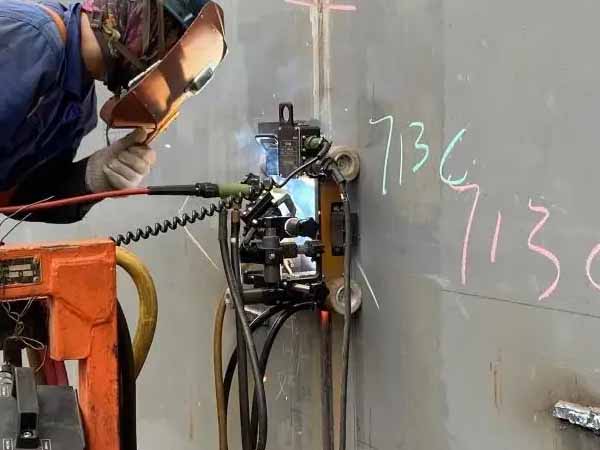
Note: This WPS is applicable for welding operations of ASTM A516 Grade 70 (A516 Gr70) carbon steel plates for medium and low temperature pressure vessels, covering conventional butt and fillet joints of medium and thick plates. It complies with ASME BPVC Sec.IX and relevant pressure vessel manufacturing specifications. The core controls include low hydrogen welding, preheating and interpass temperature, and post-weld stress relief to ensure joint strength and low temperature toughness, and eliminate defects such as cold cracks and embrittlement.
• Material Grade: ASTM A516 Grade 70 (SA516 Gr70), supplied in normalized condition.
• Material Category: High-quality low carbon pressure vessel steel, carbon equivalent CE≤0.45%, excellent weldability, low cold crack sensitivity.
• Applicable Plate Thickness: 6mm - 80mm (separate adjustment of preheating and heat treatment parameters required for extra thick plates).
• Application: Medium and low temperature pressure vessels, storage tanks, boilers, low temperature equipment.
• Design Operating Temperature: -45℃ ~ 350℃.
| Welding Method | Full Name | Applicable Scenarios | Common Joint Types | Characteristics |
|---|---|---|---|---|
| SMAW | Shielded Metal Arc Welding | Field installation, weld repair, small batch production, special-shaped joints | Butt V-groove, fillet joints | Flexible, low hydrogen electrodes recommended |
| GTAW | Gas Tungsten Arc Welding (TIG) | Root pass welding for thin-walled components, high requirement joints, single-sided welding with double-sided forming | Thin-walled butt joints, small diameter nozzles, groove root pass | Good forming, stable quality |
| GMAW | Gas Metal Arc Welding (MIG) | Automatic welding of medium and thin plates, mass production | Butt and fillet joints of medium and thick plates | High efficiency, narrow heat-affected zone |
| SAW | Submerged Arc Welding | Mass welding of longitudinal and circumferential seams for thick plates, efficiency priority scenarios | X-groove/U-groove butt joints of thick plates | Deep penetration, high efficiency, stable quality |
• Plate Thickness 6-20mm: Single V-groove, groove angle 60°±5°, root face 2-3mm, gap 2-3mm.
• Plate Thickness 20-40mm: Double V-groove, groove angle 55°±5°, root face 2-3mm, gap 2-3mm.
• Plate Thickness >40mm: U-groove, reduce welding deposition, lower welding stress.
• All grooves must be machined or ground after carbon arc gouging before welding, remove oxide scale and burrs to ensure groove smoothness.
Requirement: Low hydrogen type welding materials must be selected, with strength matching the base material and qualified low temperature toughness. Ordinary acidic welding materials are strictly prohibited to avoid weld hydrogen-induced cracks. Welding materials must have qualified quality certification documents and be compatible with the base material.
| Welding Method | AWS Welding Material Grade | Welding Material Drying and Storage Requirements |
|---|---|---|
| SMAW | E7018 (preferred), E7015 | Dry at 350-400℃ for 1h, keep warm at 100-150℃, take as needed, re-dry if unused within 4h |
| GTAW | ER70S-2, ER70S-6 | Welding wire sealed storage, remove surface oil and rust before welding, argon gas purity ≥99.99% |
| GMAW | ER70S-6 | Shielding gas: Pure CO₂ or Ar+20%CO₂ mixed gas, no leakage in gas pipeline |
| SAW | H08MnA/H10Mn2 welding wire + SJ101/SJ301 flux | Flux dried at 300-350℃ for 1h, remove oil and oxide scale from welding wire, sieving required for reused flux to remove impurities |
• Plate Thickness <25mm: Weld at room temperature (preheating 50-80℃ recommended for ambient temperature <0℃ or high restraint joints).
• Plate Thickness 25-40mm: Preheating 100-150℃.
• Plate Thickness 40-80mm: Preheating 150-200℃.
• Special Working Conditions: Increase preheating temperature by 20-50℃ for wet environment, high rigidity joints, and low temperature construction.
• Interpass Temperature Control Range: 150-250℃, strictly no more than 250℃ to avoid toughness reduction caused by coarse grains in heat-affected zone.
• Temperature Measurement Requirement: Use temperature indicator pen or infrared thermometer, temperature measurement range is 3 times the plate thickness area on both sides of the groove, temperature must be measured before each pass in multi-layer and multi-pass welding.
• Prohibition: Excessively thick single pass welding, forced welding with too low interpass temperature.
Flame uniform heating and electric heating blanket heating are recommended to ensure uniform heating of the groove area, eliminate local overheating or uneven heating; local spot rapid heating is prohibited.
| Parameter | 3.2 mm Electrode | 4.0 mm Electrode |
|---|---|---|
| Welding Current | 90-130 A | 140-180 A |
| Welding Voltage | 26-30 V | 24-28 V |
| Welding Speed | 12-18 cm/min | 15-20 cm/min |
| Polarity | DC Reverse Polarity (DC+) | DC Reverse Polarity (DC+) |
| Single Pass Thickness | 3-4 mm | 3-4 mm |
• Welding Wire Diameter: 2.0mm/2.4mm.
• Welding Current: 80-120A.
• Welding Voltage: 12-16V.
• Wire Feed Speed: 4-5m/min.
• Welding Speed: 25-35cm/min.
• Shielding Gas: Pure Argon.
• Shielding Gas Flow: 8-12L/min.
• Back Purge Argon Flow: 5-8L/min.
• Welding Wire Diameter: 1.2mm.
• Welding Current: 180-240A.
• Welding Voltage: 26-30V.
• Wire Feed Speed: 4-5m/min.
• Welding Speed: 25-35cm/min.
• Polarity: DC Reverse Polarity (DC+).
• Shielding Gas: Ar+CO₂ (CO₂: 18–25%).
• Shielding Gas Flow: 15-20L/min.
• Welding Wire Diameter: 4.0mm
• Welding Current: 450-600A
• Welding Voltage: 32-38V
• Welding Speed: 30-50cm/min
• Heat Input Control: 15-30kJ/cm
• Flux: SJ101, dried at 350℃×1h
• Flux Coverage Thickness: 30-40mm
• Pre-weld Cleaning: Thoroughly remove oil, rust, moisture and oxide scale within 20mm on both sides of the groove, grind to metallic luster to eliminate hydrogen source introduction.
• Multi-layer and Multi-pass Welding: Multi-layer and multi-pass welding must be adopted for thick plates, single pass thickness no more than 5mm, thoroughly clean slag and spatter after each pass to avoid interlayer slag inclusion.
• Back Gouging: For double-sided welding joints, perform carbon arc gouging for back gouging after front welding, grind to defect-free metal natural color before back welding to ensure full penetration.
• Welding Heat Input Control: Strictly prohibit welding with high current, wide swing and slow speed, control heat input to avoid overheating embrittlement of heat-affected zone and ensure low temperature toughness.
• Environmental Control: Welding operation environment humidity ≤90%, wind speed ≤2m/s (gas shielded welding wind speed ≤1m/s), build protective shed for windy and rainy weather, outdoor welding in severe environment is prohibited.
• Arc Striking and Termination: Strictly prohibit arc striking on base metal surface outside the groove, fill the crater during termination to prevent crater cracks.
Purpose: Eliminate welding residual stress, stabilize joint microstructure, improve low temperature toughness, prevent delayed cracks, and ensure long-term operation safety of pressure vessels.
• Plate Thickness >32mm: Mandatory post-weld stress relief heat treatment.
• Low temperature pressure vessels with design temperature below -30℃.
• High restraint joints, hydrogen sulfide corrosion environment, thick-walled pressure components.
• Heat Treatment Temperature: 595-650℃, commonly 600-620℃.
• Holding Time: 1-3min/mm, for plate thickness ≥50mm, holding time not less than 2h.
• Heating Rate: ≤200℃/h.
• Cooling Rate: ≤150℃/h, furnace cooling to below 300℃ before air cooling.
• Hardness Requirement: Hardness of weld and heat-affected zone ≤200HB, avoid brittle fracture caused by excessively high hardness.
Whole furnace heat treatment, local electric heating heat treatment. Local heat treatment must ensure uniform heating in the range of 3 times the plate thickness on both sides of the weld, temperature deviation ≤50℃.
• Uniform weld surface formation, no defects such as cracks, blowholes, slag inclusions, incomplete penetration, lack of fusion, spatter and excessive undercut.
• Undercut depth ≤0.5mm, weld reinforcement 0-3mm, fillet weld leg size must meet design requirements.
• Conventional Testing: UT (Ultrasonic Testing) or RT (Radiographic Testing) must be performed for pressure vessels, meeting ASME Level II acceptance standard.
• Surface Testing: MT (Magnetic Particle Testing) or PT (Penetrant Testing) to detect surface and near-surface cracks, mandatory for low temperature vessels.
• Testing Time: Perform 24h after welding to avoid missing delayed cracks; re-inspection can be conducted after post-weld heat treatment.
• Tensile Test: Tensile strength ≥485MPa, matching the base material.
• Bend Test: Face bend and root bend 180°, no cracks.
• Impact Test: Impact energy ≥27J at -30℃ or -45℃, meeting low temperature toughness requirements.
| Common Defects | Causes | Preventive Measures |
|---|---|---|
| Cold Cracks/Delayed Cracks | Excessively high hydrogen content, insufficient preheating, high restraint stress | Low hydrogen welding materials, strict preheating and drying, thorough hydrogen removal before welding, timely heat treatment after welding |
| Heat-Affected Zone Embrittlement | Excessively high heat input, excessively high interpass temperature, coarse grains | Control welding parameters, multi-layer and multi-pass welding, strictly control interpass temperature, PWHT, normalizing |
| Slag Inclusions/Incomplete Penetration | Inadequate interlayer cleaning, small groove angle, low current | Thorough slag cleaning, standard groove processing, matching welding current |
| Insufficient Low Temperature Toughness | Poor welding material toughness, no heat treatment, uncontrolled heat input | Select high toughness welding materials, strict temperature control, PWHT, refined welding |
This WPS is a recommended reference process by engineers. Actual construction requires parameter fine-tuning according to product design requirements, plate thickness and on-site working conditions. Welding Procedure Qualification (PQR) must be completed before welding, welders must hold valid certificates and strictly implement this specification. Special welding schemes must be prepared separately for extra thick plates, special joints and extreme low temperature environments.
Compilation Date: 2026.03.24
Applicable Specifications: ASME BPVC Sec.IX, ASTM A516, Relevant Standards for Pressure Vessel Welding.
Customers choose to engage in long-term cooperation with Yuxin Steel not only because of our high-quality products and services, as well as our strong reputation in the international market, but also due to our experienced one-stop raw material supply and further steel processing capabilities!