ABS Grade B Marine Structural Steel Welding Process Guide
- Apr 22, 2026
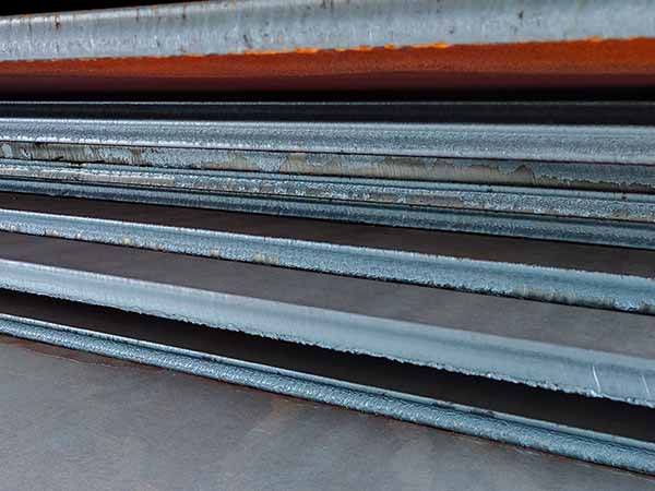
ABS Grade B is a standard-strength marine structural steel certified by the American Bureau of Shipping (ABS), suitable for non-high-strength load-bearing structures such as hulls, decks and ship’s sides. Its carbon equivalent is ≤0.36%; it has low susceptibility to cold cracking and good weldability. Preheating is generally not required, but the classification society’s welding specifications must be strictly adhered to.
| C | Si | Mn | P | S | Cu | Cr | Ni |
|---|---|---|---|---|---|---|---|
| ≤ 0.21 | ≤ 0.35 | ≥ 0.80 | ≤ 0.035 | ≤ 0.035 | ≤ 0.35 | ≤ 0.30 | ≤ 0.30 |
| Grade | Yield Strength (ReH), MPa | Tensile Strength (Rm), MPa | Elongation (A), % | Impact Energy (KV2 / J, at 0℃) | |
|---|---|---|---|---|---|
| Longitudinal | Transverse | ||||
| ABS Grade B | ≥ 235 | 400 - 520 | 22 | 27 | 20 |
Carbon equivalent (CEV) (IIW): ≤0.36%
Low susceptibility to cold cracking: thin plates (≤20 mm) can be welded at room temperature; preheating is recommended for thick plates and in low-temperature environments.
Manual arc welding (SMAW): Repair, positioning, confined spaces.
Submerged arc welding (SAW): Flat butt joints, long straight seams (high efficiency, high quality).
CO₂ gas shielded arc welding (GMAW/FCAW): Hull structures, fillet joints / butt joints (mainstream).
Tungsten inert gas welding (GTAW): Root passes, thin-walled sections, applications requiring high-quality bead formation.
(1) Manual Arc Welding (Electrodes)
Type: E43 series (AWS E6015/E6016)
Grades: J426, J427, CHE427 and other low-hydrogen electrodes
Drying: 300–350°C × 1h, hold at 100–150°C; use as required
(2) Gas Shielded Arc Welding (Solid / Flux-Cored)
Solid wire (GMAW): ER50-6 (AWS ER70S-6), φ1.0/1.2 mm
Shielding gas: CO₂ (≥99.5%) or 80% Ar + 20% CO₂
Flux-cored wire (FCAW): E501T-1/E501T-5 (commonly used in shipbuilding)
(3) Submerged arc welding (SAW)
Welding wire: H08A/H08MnA
Flux: HJ431/SJ101 (neutral / basic)
t < 12 mm: I-groove, gap 0–2 mm
t ≥ 12 mm: V-groove, angle 60°±5°, fillet 1–2 mm, gap 2–3 mm
t > 25 mm: X-groove (double-sided welding to minimise welding distortion)
Rust, oil, paint, scale and moisture must be thoroughly removed from the groove and the area extending ≥20mm on either side; the surface must be ground to a metallic sheen. In low-temperature, high-humidity environments, preheating and dehumidification (50–80°C) are required.
| Plate thickness (mm) | Preheating requirement | Interpass temperature |
|---|---|---|
| t ≤ 20 | Generally no preheating (50℃ recommended when ambient temperature <5℃) | ≤ 200℃ |
| 20 < t ≤ 40 | 50-75℃ | ≤ 200℃ |
| t > 40 | 75-100℃ | ≤ 220℃ |
Special operating conditions: In environments where humidity exceeds 80% or temperatures fall below 0°C, the unit must be preheated to above 50°C and moisture must be removed.
Tack weld length 30–50 mm, spacing 200–300 mm, tack welds ≤ 2/3 of the design tack welds; No defects such as porosity, cracks or inclusions are permitted; any defects must be ground out and the weld re-welded.
| Plate thickness (mm) | Electrode diameter φ (mm) | Current (A) | Voltage (V) | Polarity |
|---|---|---|---|---|
| 3–5 | 3.2 | 90–130 | 22–26 | DC+ |
| 6–12 | 4.0 | 140–180 | 24–28 | DC+ |
| ≥14 | 5.0 | 180–220 | 26–30 | DC+ |
| Position | Current (A) | Voltage (V) | Speed (cm/min) | Gas Flow (L/min) |
|---|---|---|---|---|
| Flat / Horizontal | 220–280 | 28–32 | 35–50 | 15–20 |
| Vertical / Overhead | 120–180 | 24–28 | 25–35 | 18–22 |
| Current (A) | Voltage (V) | Speed (cm/min) | Flux |
|---|---|---|---|
| 550–650 | 32–38 | 40–60 | Drying: 300–350 °C for 1–2 hours |
Single-pass weld thickness ≤ 4 mm; single-pass width ≤ 5 times the wire diameter; thick plates must be welded using multi-pass welding, with scale removed and defects inspected after each pass.
Flat welding: Use straight or slight oscillating stick movement; travel angle 70–80°
Vertical-up welding: Weld from bottom to top using low current and short-arc technique
Fillet welding: Tilt the torch at 45° towards the base metal to ensure good fusion
The arc must be struck within the groove; striking the arc on the non-welded area of the base metal is strictly prohibited. When extinguishing the arc, the crater must be filled to prevent crater cracking; the extinguishing point must overlap the previous weld bead by 10–20 mm.
5.4 Deformation Control
Deformation shall be controlled by means of reverse bevel (1–3°), rigid clamping, symmetrical welding and segmented back-welding; for long welds, segmented skip welding shall be used, with each segment measuring 300–500 mm in length.
ABS Grade B generally does not require post-weld heat treatment; however, stress-relief annealing at 600–650°C with a holding time of 1–2 hours per millimetre is recommended in the following cases:
Thick plates (>30 mm) in highly constrained structures
Structures intended for service in low-temperature or corrosive environments
Areas sensitive to welding residual stresses
The weld bead shall be uniform in shape, free from defects such as cracks, porosity, inclusions and lack of fusion; undercut >0.5 mm shall be ground; weld height 0–3 mm; fillet dimension tolerance ±1 mm.
Critical structures: 100% ultrasonic testing (UT) or magnetic particle testing (MT)
Fillet welds and non-critical structures: Sampling for MT/PT testing
Acceptance criteria: ABS Rules for Materials and Welding Part 2
| Defect | Cause | Preventive Measure |
|---|---|---|
| Porosity | Poor cleaning, impure gas, moisture | Thorough cleaning, dry gas, dry electrodes |
| Crack | Fast cooling, high stress, hydrogen-induced | Preheating, low-hydrogen electrodes, slow cooling, stress relief |
| Incomplete penetration | Small groove, low current, high speed | Standardized groove, matched parameters, controlled oscillation |
| Slag inclusion | Poor interpass cleaning, low current | Clean each layer, increase current appropriately |
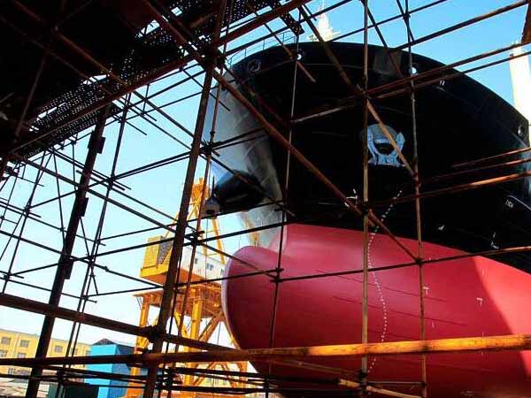
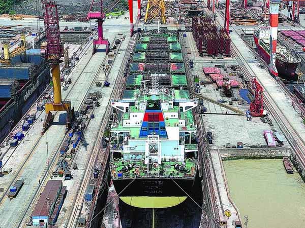
Scope of Application: Hull structures, decks, bulkheads, slipways, etc., of ABS-certified ships and offshore structures
Applicable Standards: ABS Rules for Materials and Welding (Part 2); AWS A5.1/A5.18 Specification for Carbon Steel Electrodes for Shielded Metal Arc Welding
Customers choose to engage in long-term cooperation with Yuxin Steel not only because of our high-quality products and services, as well as our strong reputation in the international market, but also due to our experienced one-stop raw material supply and further steel processing capabilities!